Contents
General description
The hardware used to convert the digital signals from the EVLA
antennas into analog signals to be fed into the VLA correlator causes
power to be aliased into the bottom 0.5 MHz of baseband. This affects
all sources with continuum emission, most notably, commonly-used gain
calibrators. The aliased power is strongest at the very bottom of
baseband, and decreases away from baseband. For all bands except X
and U band on the VLA, the bottom of baseband is at low-numbered
channels. For X and U band, the bottom of baseband occurs at
high-numbered channels. This problem obviously affects the narrowest
observing bandwidths the most, with bandwidth codes 6 (781 kHz total
bandwidth, typically the narrowest commonly used on the VLA) and
higher being affected over the full width of the band. Although we
are investigating ways to mitigate this problem, it is likely that the
effect will remain with us until the new EVLA correlator comes online.
In fact, the problem will affect more and more baselines as more VLA
antennas are retrofitted to EVLA antennas. Note that since the
aliased signal does not correlate on VLA-EVLA baselines, only
EVLA-EVLA baselines are affected.
This is illustrated in Figure 1 which shows the response across the
band for two baselines; one with antennas 1 and 13 (EVLA - EVLA) and
one with antenna 6 and 13 (VLA - EVLA). This example is at L-band,
but it occurs at any band. In this case, the contribution of the
aliasing is negative: the signal increases with increasing frequency
to reach a constant level after 0.5 MHz. For other baselines, the
effect can be positive, where the signal decreases with increasing
frequency to reach a constant level after 0.5 MHz.
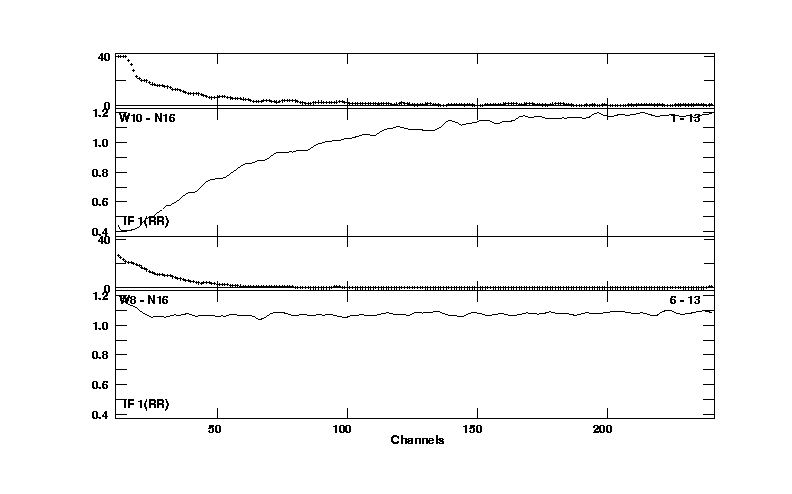 Figure 1: Response across a 0.78 MHz band for an EVLA - EVLA
(antennas 1 and 13) baseline (top) and a VLA - EVLA (antennas 6 and
13) baseline (bottom).
Figure 1: Response across a 0.78 MHz band for an EVLA - EVLA
(antennas 1 and 13) baseline (top) and a VLA - EVLA (antennas 6 and
13) baseline (bottom).
Impact on observing
A necessary condition for aliasing to occur is that there be emission
between 0 and 0.5 MHz below the bottom of baseband. This is generally
the case for continuum emission but rarely so for line emission.
Nonetheless, aliasing has the following consequences:
- Whereas the actual line emission may not suffer from aliasing
directly, the phase and bandpass calibrators are continuum sources,
and will therefore be affected over the first 0.5 MHz above baseband
(or last 0.5 MHz below baseband for X band). We distinguish the
following two cases:
- After excluding the affected 0.5 MHz, there still is sufficient
bandwidth available to form a continuum for calibration purposes.
In that case, form a new 'channel 0' by running the AIPS task AVSPC on
the spectral line data, while making sure to exclude the affected 0.5
MHz. Use this new 'channel 0' as input for calibration tasks such as
CALIB and CLCAL.
- After excluding the affected 0.5 MHz, there isn't sufficient
bandwidth available to form a continuum for calibration purposes.
In that case, all data from EVLA-EVLA baselines must be ignored during
calibration. This can be done by flagging all EVLA-EVLA baselines
prior to calibration, e.g. by using UVFLG with OPCODE='FLAG' and a
unique choice for the adverb REASON. Note that in this way EVLA
antenna gains are still being determined, but based on VLA-EVLA
baselines only. After the full calibration (including bandpass) is
complete, the EVLA-EVLA baselines need to be unflagged, again using
UVFLG, now with OPCODE='UFLG', and the same value of REASON as was
used when flagging them.
For subarrays containing only EVLA antennas the above will clearly not
work, and methods for calibrating these data are under investigation.
- In most cases, the field of view will contain both line and
continuum emission, and removing the continuum requires extra care.
The aliased continuum can be subtracted in the visibility plane using
the AIPS task UVLSF, just as has been common practice in the past for
data not affected by aliasing. However, in order to fit the shape of
the aliased continuum, a high order fit is needed. The latest version
of UVLSF now supports orders up to 4, and users will need to make sure
they have run a Midnight Job since October 31, 2007, to obtain this
version. It is our experience that a fourth order fit is required and
sufficient to properly represent the aliased continuum. Note that
while the line signal can be recovered this way, this is not the case
for the continuum as there is no way to separate the aliased part of
the continuum from the unaffected part. We have received reports,
though, that running BLCAL can improve the resulting continuum, but
this requires frequent observations of a strong calibrator.
Clearly, a higher order polynomial fit will only work if there is a
sufficient number of line-free channels at either end to base the fit
on. We recommend that at least one-quarter of the total bandwidth at
either end is line-free. In other words, the total number of channels
with line emission should not exceed 50% of the total number of
channels.
A successful fit requires aliased signal to base the fit on. This may
not be the case if the field of view does not contain strong continuum
sources. We are considering implementing AIPS software that will
perform the UVLSF fit on calibrators only, and subtract a properly
scaled version of this aliased response from the source data. In
anticipation of such a task, we strongly recommend all spectral line
observers planning to use narrow bandwidths to give higher weight to
strength than to vicinity to the source, when deciding which phase
calibrator to use.
Note that it is almost certainly impossible to stitch together narrow
bands to obtain wider frequency/velocity coverage for wide spectral
lines, because there is no way to subtract the aliased continuum
signal in this case. Also, the line emission below baseband will be
aliased into the band in an unpredictable way depending on the shape
and strength of the emission line.
- In all cases, noise is aliased into the band and will decrease
the effective sensitivity, with the channels closest to baseband
being the most affected.
Typical cases
- Bandstitching
Bandstitching is the technique using IFs partially overlapping
in frequency, e.g.:
        IF A   |----------------------|
        IF B                   |----------------------|
                         ^^^^^^^
Since any line emission in the 0.5 MHz wide region indicated
by ^^^^^^^ will get aliased into
IF B, this method is strongly discouraged. Any project trying
to use bandstitching should instead use a wider bandwidth code
and include all the line in one IF setting.
- Emission line+continuum experiments
Any emission line+continuum experiment will have the continuum
affected but not the line. In this case it depends on whether the
continuum emission itself is needed, or just needs to be
subtracted.
- If the continuum matters, 195 kHz bandwidth mode is
impossible; there are no unaliased channels from which to
estimate the true continuum level. If a factor of 2-4
increase in channel width can still achieve the science, we
recommend 781 kHz instead. The continuum should be derived
from a fit to a channel as far away from baseband as possible
using the AIPS task UVLSF and the adverb CHANNEL to specify
the channel.
- If the continuum just needs to be subtracted, make sure
there are enough line-free channels. A different bandwidth
may be needed to achieve this.
- Emission line only (no continuum) experiments
Any line-only experiment will be OK, except that calibrators
will be affected, and EVLA-EVLA baselines will need to be
flagged during calibration.
- Absorption line experiments
Absorption line experiments requesting 195 kHz mode cannot be
done, for the same reason as emission+continuum above; there
are no unaliased channels from which to estimate the true
continuum level. In this case, a wider bandwidth code is
recommended.
Other absorption line experiments should be OK provided the
continuum is derived from a UVLSF fit to an unaliased channel
far from baseband.
- EVLA-only subarray
Bandwidths of 781 kHz and larger can probably be done, but with
significant increase in noise at baseband that will need to be
compensated by extra integration time unless line emission can
be moved to an unaliased part of the bandpass.
- General
In all cases,
- Make sure there are enough line-free channels to
accommodate a 4th order polynomial fit.
- Consider whether an emission/absorption line might be
moved away from baseband to an unaliased part of the
bandpass.
What can be done in post-processing
A new task FIXAL has been added to AIPS which fits observations of
calibrator sources to determine the aliasing function and then fits
that function to line-free channels in the main data set to determine
alias-free amplitude and phase, and to correct the data for the
aliasing. A procedure FXALIAS was written to assist in the
operation. It runs BPASS using only VLA-VLA and VLA-EVLA baselines,
applies the bandpass to all data with SPLAT, separates the bandpass
calibrators with UVCOP, and then runs FIXAL. Note that this operation
must be done on totally uncalibrated data: if any phase correction has
been applied, the above formula will have been rendered incorrect.
At present, the new task and procedure should be regarded as highly
experimental. They appear to work most of the time and to remove most
of the problem. There are niggling bits left and there are cases in
which they do not work well. In general we recommend observers to
plan their observations in such a way (i.e. not needing the aliased
part of the spectrum in any post-processing) that they do not have to
rely on post-processing to get rid of effects of kaliasing.
See the relevant section of the 30JUN08
AIPSLetter, and the AIPS HLP files for FXAL and FXALIAS for
further details. This continues an area of further study and user
feedback to our support
staff is appreciated.
|
